Gear Types and Gear Ratios
What are gears used for?
Gears play a huge role in much of the technology around today. For example, car engines, drills, lathes, mills, cd/dvd players, printers, mechanical watches, children's toys, in fact gears are almost everywhere there are motors and engines which produce a rotational movement.
Gears are excellent at keeping the rotation of two axis in sync. Where a belt and pulley system would eventually run out of sync due to a slight inaccuracy in the diameter of pulleys, a geared system will always stay in sync regardless of slight inaccuracies, this is due to the meshing of the gear teeth forcing gears to rotate consistently with one another.
•They are used to reverse direction of rotation, for example when selecting reverse in your car.
•Gears are also used to transfer rotational motion to a different axis.
•Gears are used to alter the speed of rotation which in the same way can be used to alter the end turning force or torque available.
Understanding Gear Ratios
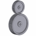
The animation above shows two gears in mesh, imagine gear 'A' is driving gear 'B'.
Because gear "A" has 20 teeth and "B" has 40 teeth "A" will travel through two complete turns for every one complete turn of gear "B" this would give a ratio of 1:2. This is because gear "A's" rotational speed is half that of gear "B".
If things were the other way around and gear "B" was driving gear "A"
then the ratio would become 2:1 as the end rotational speed has been doubled at "A".
Gear Types
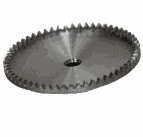
Spur
 |
Spur gears are a simple gear type, they take the form of a cylinder or disk with their teeth formed around the gears circumference, spur gears can be meshed together on parallel axles. |
Bevel
 |
Bevel gears have a cone shape which enables them to mesh at various angles except 0 and 180 degrees, that is not to say a single bevel gear can work at multiple angles, the bevel gears must be cut to suit a specific meshing angle. The teeth of a bevel gear can be straight cut, similar to that of a spur gears teeth, or they can be curved along their length with each tooth sitting at an angle (Spiral bevel gear). Zerol bevel gears are too curved along their length but are not angled. Bevel gears are suited best to low speed applications usually sub 5m/s. |
Worm drive
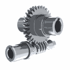
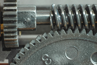
|
The worm resembles the thread of a screw, and are usually meshed with a worm wheel which looks similar to a typical spur gear. Worm gears are an excellent way to increase torque output while reducing rotational speed. Worm drives have ratios varying from around 10:1 to 500:1, worm gears do have a slight disadvantage in that they are not very efficient, a lot of energy can be wasted due to the sliding action of the gear teeth. The worm itself can have 1 or more teeth, although 1 tooth that follows around the length of the worm several times can look like more than one tooth being present. A worm with one tooth is called a single thread or single start, while a worm with more than one tooth is called a multiple thread or multiple start. |
Crown
 |
Crown gears are a form of bevel gears, the teeth of crown gears project at right angles to the plane of the wheel. Crown gears are usually meshed with another bevel gear, but in some instances are meshed with spur gears. |
Helical
|
Helical gears have angled teeth which form a curve that resembles a segment of a helix. Helical gears are meshed in parallel or crossed orientations and are used because they offer a more refined operation and run much smoother and quieter than spur gears for example. Helical gears can operate at high speeds and transmit large amounts of torque.
A disadvantage of helical gears is the thrust generated by the curved teeth when under load, this is usually handled by a suitable thrust bearing to help take this load. |
Double helical
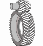 |
A double helical gear is similar to 2 separate helical gears joined together but mirrored, this helps eliminate the thrust that a single helical gear would create as in effect there is equal thrust in each direction cancelling each other out. |
| Rack and pinion
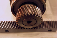
|
A rack and pinion system is used to transfer rotational movement into linear movement. The pinion which is the circular gear drives the rack (the straight toothed section) in a linear direction. Typically the pinion is used to drive the rack but this is not always the case. Examples of rack and pinion use include stair lifts, car steering, lock gates. |
|